


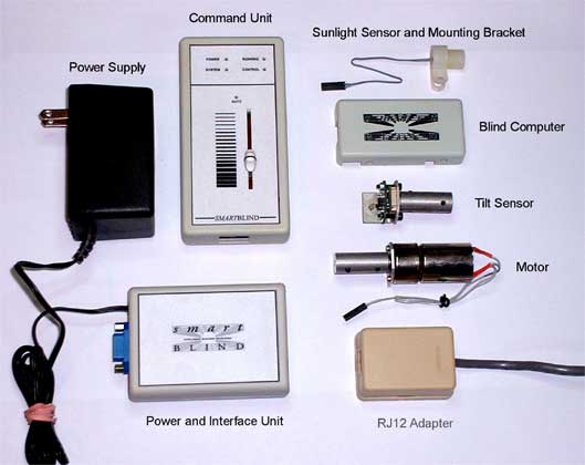
The smartBLIND system
- one 24VDC, 1 Amp, wall mount Power Supply
- one Power and Interface Unit
- one Command Unit
- one RJ12 Adapter
- one Sunlight Sensor
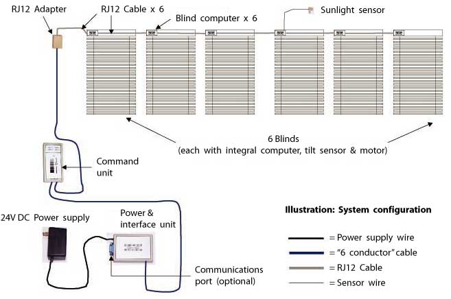
- one or more blinds, up to 6 maximum (including blind computer, tilt sensor, and motor)
- a length of “6 conductor” cable
- RJ12 cables of a specific length
(As many RJ12 cables will be required as there are blinds in the system,up to a maximum of 6.)
Additional options
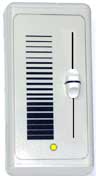
Local Command Unit
This device operates in the same manner as the system Command Unit but is specific to a single blind. It connects to the individual blind computer via a sub-miniature, four-pin connector and is wall-mounted near the blind it will control. When this device is operated, it will override any system commands and will move the individual blind to the requested position. A small LED (shown) indicates if the blind is currently under system control (LED is lit) or is in manual mode (LED is not lit).
Each blind in the smartBLIND system has the potential to include the Local Command Unit option.
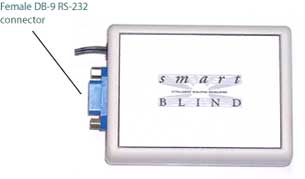
RS-232 Remote Computer Interface
This device allows remote computer control of the entire smartBLIND system.
Each blind in the system is individually addressable by the remote computer, and the remote computer can direct individual blinds to move to a requested position at either high speed (immediate change) or low speed (imperceptible motion).
The remote computer can also request all blinds to move simultaneously to a requested position (global command) at either high or low speed.
The remote computer can also request data from the smartBLIND system (sunlight intensity, system health, etc.).